What does heart rate mean on ecg. ECG interpretation, normal indicators. Indications for an ECG
Electrocardiographic examination is a fairly simple and effective method diagnostics, used by cardiologists around the world to study the activity of the heart muscle. The results of the procedure in the form of graphs and numerical symbols, as a rule, are transferred to specialists for further data analysis. However, if, for example, the necessary doctor is not available, the patient has a desire to independently decipher his heart parameters.
Preliminary interpretation of an ECG requires knowledge of special basic data, which, due to its specificity, is not within the power of everyone. In order to make correct calculations ECG of the heart a person who is not related to medicine needs to become familiar with the basic principles of processing, which are combined for convenience into appropriate blocks.
Introduction to the basic elements of a cardiogram
You should know that the interpretation of the ECG is carried out thanks to elementary, logical rules that can be understood even by the average person. For a more pleasant and calm perception of them, it is recommended to start familiarizing yourself first with the simplest principles of decoding, gradually moving to a more complex level of knowledge.
Tape marking
The paper on which data on the functioning of the heart muscle is reflected is a wide ribbon of a soft pink shade with a clear “square” marking. Larger quadrangles are formed from 25 small cells, and each of them, in turn, is equal to 1 mm. If a large cell is filled with only 16 dots, for convenience you can draw parallel lines along them and follow similar instructions.
The horizontal lines of the cells indicate the duration of the heartbeat (seconds), and the vertical lines indicate the voltage of individual ECG segments (mV). 1 mm is 1 second of time (in width) and 1 mV of voltage (in height)! This axiom must be kept in mind throughout the entire period of data analysis; later its importance will become obvious to everyone.
The paper used allows you to accurately analyze periods of time
Teeth and segments
Before moving on to the names of specific departments of the dentate graph, it is worth familiarizing yourself with the activity of the heart itself. The muscular organ consists of 4 compartments: the 2 upper ones are called atria, the 2 lower ones are called ventricles. Between the ventricle and the atrium in each half of the heart there is a valve - a valve responsible for accompanying the flow of blood in one direction: from top to bottom.
This activity is achieved thanks to electrical impulses that move through the heart according to a “biological schedule”. They are directed to specific segments of the hollow organ using a system of bundles and nodes, which are miniature muscle fibers.
The birth of the impulse occurs in the upper part of the right ventricle - the sinus node. Next, the signal passes to the left ventricle and excitation of the upper parts of the heart is observed, which is recorded by the P wave on the ECG: it looks like a flat inverted bowl.
After the electrical charge reaches the atrioventricular node (or AV node), located almost at the junction of all 4 pockets of the heart muscle, a small “point” appears on the cardiogram, directed downwards - this is the Q wave. Just below the AV node there is the following point the destination of the impulse is the His bundle, which is fixed by the highest R wave among others, which can be imagined as a peak or mountain.
Having overcome half the path, an important signal rushes to the lower part of the heart, through the so-called branches of the His bundle, which externally resemble long octopus tentacles that hug the ventricles. The conduction of the impulse along the branching processes of the bundle is reflected in the S wave - a shallow groove at the right foot of R. When the impulse spreads to the ventricles along the branches of the His bundle, their contraction occurs. The last hummocky T wave marks the recovery (rest) of the heart before the next cycle.

Not only cardiologists, but also other specialists can decipher diagnostic indicators
In front of the 5 main waves on the ECG you can see a rectangular protrusion; you should not be afraid of it, since it represents a calibration or control signal. Between the teeth there are horizontally directed sections - segments, for example, S-T (from S to T) or P-Q (from P to Q). To independently make an approximate diagnosis, you will need to remember such a concept as the QRS complex - the union of the Q, R and S waves, which records the work of the ventricles.
The teeth that rise above the isometric line are called positive, and those located below them are called negative. Therefore, all 5 teeth alternate one after another: P (positive), Q (negative), R (positive), S (negative) and T (positive).
Leads
You can often hear the question from people: why are all the graphs on the ECG different from each other? The answer is relatively simple. Each of the curved lines on the tape reflects heart parameters obtained from 10-12 colored electrodes, which are installed on the limbs and in the chest area. They read data on the cardiac impulse, located at different distances from the muscle pump, which is why the graphs on the thermal tape are often different from each other.
Only an experienced specialist can competently write an ECG report, but the patient has the opportunity to review general information about your health.
Normal cardiogram values
Now that it has become clear how to decipher the cardiogram of the heart, we should begin to directly diagnose normal readings. But before you get acquainted with them, you need to evaluate the ECG recording speed (50 mm/s or 25 mm/s), which, as a rule, is automatically printed on paper tape. Then, based on the result, you can view the norms for the duration of teeth and segments, which are listed in the table (calculations can be carried out using a ruler or checkered markings on a tape):
Among the most significant provisions for ECG interpretation are the following:
- S-T segments and P-Q should “merge” with the isometric line without going beyond it.
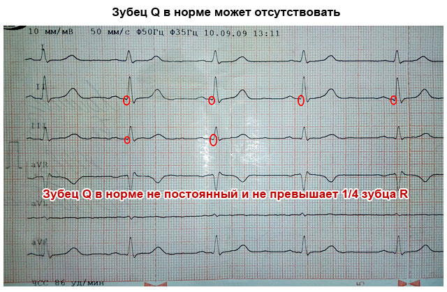
- The depth of the Q wave cannot exceed ¼ of the height of the slenderest wave - R.
- The exact parameters of the S wave have not been approved, but it is known that it sometimes reaches a depth of 18–20 mm.
- The T wave should not be higher than R: its maximum value is ½ the height of R.
Control of heart rhythm is also important. It is necessary to pick up a ruler and measure the length of the segments between the vertices R: the results obtained must coincide with each other. To calculate heart rate (or heart rate), you should count the total number of small cells between the 3 vertices of R and divide the digital value by 2. Next, you need to apply one of 2 formulas:
- 60/X*0.02 (at a recording speed of 50 mm/sec).
- 60/X*0.04 (at a recording speed of 25 mm/sec).
If the number is in the range from 59–60 to 90 beats/min, then the heart rate is normal. An increase in this index implies tachycardia, and a clear decrease implies bradycardia. If for a mature person a heart rate of more than 95–100 beats/min is a rather dubious sign, then for children under 5–6 years old this is one of the varieties of the norm.

Each of the teeth and intervals indicates a certain period of time the heart muscle is working
What pathologies can be identified when decoding data?
Although the ECG is one of the extremely simple studies in structure, there are still no analogues for such a diagnosis of cardiac abnormalities. You can become familiar with the most “popular” diseases recognized by ECG by examining both the description of their characteristic indicators and detailed graphic examples.
This disease is often recorded in adults during ECG, but in children it manifests itself extremely rarely. Among the most common “catalysts” of the disease are the use of drugs and alcohol, chronic stress, hyperthyroidism, etc. PT is distinguished, first of all, by a frequent heartbeat, the indicators of which range from 138–140 to 240–250 beats/min.
Due to the occurrence of such attacks (or paroxysms), both ventricles of the heart do not have the opportunity to fill with blood in time, which weakens the overall blood flow and slows down the delivery of the next portion of oxygen to all parts of the body, including the brain. Tachycardia is characterized by the presence of a modified QRS complex, a weakly expressed T wave and, most importantly, the absence of a distance between T and P. In other words, groups of waves on the electrocardiogram are “glued” to each other.

The disease is one of the “invisible killers” and requires immediate attention to a number of specialists, since if left untreated it can lead to death
Bradycardia
If the previous anomaly implied the absence T-P segment, then bradycardia is its antagonist. This disease is indicated by a significant prolongation of T-P, indicating weak conduction of the impulse or its incorrect accompaniment through the heart muscle. In patients with bradycardia, extreme low index Heart rate – less than 40–60 beats/min. If in people who give preference to regular physical activity, a mild manifestation of the disease is the norm, then in the vast majority of other cases we can talk about the onset of an extremely serious disease.
If obvious signs of bradycardia are detected, you should undergo comprehensive examination.
Ischemia
Ischemia is called a harbinger of myocardial infarction; for this reason, early detection of an anomaly contributes to the relief of a fatal ailment and, as a result, a favorable outcome. It was previously mentioned that the S-T interval should “lie comfortably” on the isoline, but its descent in the 1st and AVL leads (up to 2.5 mm) signals precisely IHD. Sometimes coronary heart disease produces only the T wave. Normally, it should not exceed ½ the height of R, however, in this case it can either “grow” to the senior element or fall below the midline. The remaining teeth do not undergo significant changes.
Atrial flutter and fibrillation
Atrial fibrillation is an abnormal condition of the heart, expressed in an erratic, chaotic manifestation electrical impulses in the upper pockets of the heart. It is sometimes not possible to make a qualitative superficial analysis in such a case. But knowing what you should pay attention to first, you can calmly decipher the ECG indicators. The QRS complexes are not of fundamental importance, since they are often stable, but the gaps between them are key indicators: when flickering, they resemble a series of notches on a handsaw.

Pathologies are clearly distinguishable on a cardiogram
Not so chaotic, large-sized waves between QRS already indicate atrial flutter, which, unlike flicker, is characterized by a slightly more pronounced heartbeat (up to 400 beats/min). Contractions and excitations of the atria are to a small extent subject to control.
Thickening of the atrial myocardium
Suspicious thickening and stretching of the muscle layer of the myocardium is accompanied by a significant problem with the internal blood flow. At the same time, the atria perform their main function with constant interruptions: the thickened left chamber “pushes” blood into the ventricle with greater force. When trying to read an ECG graph at home, you should focus your attention on the P wave, which reflects the condition of the upper parts of the heart.
If it is a kind of dome with two bulges, most likely the patient is suffering from the disease in question. Since thickening of the myocardium in the long-term absence of qualified medical intervention provokes a stroke or heart attack, it is necessary to make an appointment with a cardiologist as soon as possible with the provision of detailed description discomfort symptoms, if any.
Extrasystole
It is possible to decipher an ECG with the “first signs” of extrasystole if you have knowledge about special indicators special manifestation of arrhythmia. By carefully examining such a graph, the patient may detect unusual abnormal surges that vaguely resemble QRS complexes - extrasystoles. They occur in any area of the ECG, and are often followed by a compensatory pause, allowing the heart muscle to “rest” before starting a new cycle of excitations and contractions.
Extrasystole in medical practice often diagnosed in healthy people. In the vast majority of cases, it does not affect the usual course of life and is not associated with serious illnesses. However, when arrhythmia is detected, you should play it safe by contacting specialists.
With atrioventricular heart block, an expansion of the gap between the P waves of the same name is observed, in addition, they can occur at the time of analysis of the ECG conclusion much more often than QRS complexes. Registration of such a pattern indicates low conductivity of the impulse from the upper chambers of the heart to the ventricles.

If the disease progresses, the electrocardiogram changes: now the QRS “falls out” of the general row of P waves in some intervals
Bundle branch block
Failure in the operation of such an element of the conduction system as the His bundle should in no case be ignored, since it is located in close proximity to the Myocardium. In advanced cases, the pathological focus tends to “spill over” to one of the most important areas of the heart. It is quite possible to decipher the ECG yourself in the presence of an extremely unpleasant disease; you just need to carefully examine the highest tooth on the thermal tape. If it does not form a “slender” letter L, but a deformed M, this means that the His bundle has been attacked.
Damage to its left leg, which passes the impulse into the left ventricle, entails the complete disappearance of the S wave. And the place of contact of the two vertices of the split R will be located above the isoline. Cardiographic image of attenuation right leg The beam is similar to the previous one, only the connection point of the already designated vertices of the R wave is located under the midline. T is negative in both cases.
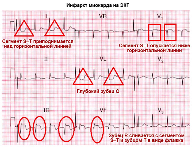
Myocardial infarction
The myocardium is a fragment of the densest and thickest layer of the heart muscle, which last years exposed to various ailments. The most dangerous among them is necrosis or myocardial infarction. When deciphering electrocardiography, it is sufficiently distinguishable from other types of diseases. If the P wave, which registers the good condition of the 2 atria, is not deformed, then the remaining ECG segments have undergone significant changes. Thus, a pointed Q wave can “pierce” the isoline plane, and a T wave can be transformed into a negative wave.
The most indicative sign of a heart attack is an unnatural elevation of R-T. There is a mnemonic rule that allows you to remember its exact appearance. If, when examining this area, one can imagine the left, ascending side of R in the form of a rack tilted to the right, on which a flag is flying, then we are really talking about myocardial necrosis.

The disease is diagnosed both in the acute phase and after the attack has subsided.
Ventricular fibrillation
Otherwise, an extremely serious illness is called atrial fibrillation. A distinctive feature of this pathological phenomenon is considered to be the destructive activity of conductive bundles and nodes, indicating uncontrolled contraction of all 4 chambers of the muscle pump. Reading the ECG results and recognizing ventricular fibrillation is not at all difficult: on a checkered tape it appears as a series of chaotic waves and valleys, the parameters of which cannot be correlated with classical indicators. In none of the segments is it possible to see at least one familiar complex.
If a patient with atrial fibrillation is not treated prematurely medical care, he will die soon.
WPW syndrome
When, in the complex of classical pathways for conducting an electrical impulse, an abnormal bundle of Kent unexpectedly forms, located in the “comfortable cradle” of the left or right atrium, we can confidently speak about a pathology such as WPW syndrome. As soon as the impulses begin to move along the unnatural cardiac highway, the rhythm of the muscle is lost. The “correct” conducting fibers cannot fully supply the atria with blood, because the impulses prefer a shorter path to complete the functional cycle.
The ECG with SVC syndrome is characterized by the appearance of a microwave at the left foot of the R wave, a slight widening of the QRS complex and, of course, a significant reduction in the P-Q interval. Since deciphering the cardiogram of a heart that has undergone WPW is not always effective, the HM - Holter method of diagnosing the disease - comes to the aid of medical personnel. It involves wearing a compact device with sensors attached to the skin around the clock.
Long-term monitoring provides a better result with a reliable diagnosis. In order to timely “catch” an anomaly localized in the heart, it is recommended to visit the ECG room at least once a year. If regular medical monitoring of the treatment of cardiovascular disease is necessary, more frequent measurements of cardiac activity may be required.
From this article you will learn about such a diagnostic method as an ECG of the heart - what it is and what it shows. How an electrocardiogram is recorded, and who can most accurately decipher it. You will also learn how to independently determine the signs of a normal ECG and major heart diseases that can be diagnosed using this method.
Article publication date: 03/02/2017
Article updated date: 05/29/2019
What is an ECG (electrocardiogram)? This is one of the simplest, most accessible and informative methods diagnosis of heart diseases. It is based on recording electrical impulses arising in the heart and graphically recording them in the form of teeth on a special paper film.
Based on these data, one can judge not only the electrical activity of the heart, but also the structure of the myocardium. This means that an ECG can diagnose many different heart conditions. Therefore, independent interpretation of the ECG by a person who does not have special medical knowledge is impossible.
All that an ordinary person can do is only roughly assess the individual parameters of the electrocardiogram, whether they correspond to the norm and what pathology they may indicate. But final conclusions based on the ECG conclusion can only be made by a qualified specialist - a cardiologist, as well as a therapist or family doctor.
Principle of the method
The contractile activity and functioning of the heart is possible due to the fact that spontaneous electrical impulses (discharges) regularly occur in it. Normally, their source is located in the uppermost part of the organ (in the sinus node, located near the right atrium). The purpose of each impulse is to travel along the nerve pathways through all parts of the myocardium, causing them to contract. When an impulse arises and passes through the myocardium of the atria and then the ventricles, their alternating contraction occurs - systole. During the period when there are no impulses, the heart relaxes - diastole.
ECG diagnostics (electrocardiography) is based on recording electrical impulses arising in the heart. For this purpose, a special device is used - an electrocardiograph. The principle of its operation is to capture on the surface of the body the difference in bioelectric potentials (discharges) that occur in different parts of the heart at the moment of contraction (in systole) and relaxation (in diastole). All these processes are recorded on special heat-sensitive paper in the form of a graph consisting of pointed or hemispherical teeth and horizontal lines in the form of spaces between them.

What else is important to know about electrocardiography
Electrical discharges of the heart pass not only through this organ. Since the body has good electrical conductivity, the strength of the exciting cardiac impulses is sufficient to pass through all tissues of the body. They spread best to the chest in the area, as well as to the upper and lower limbs. This feature is the basis of the ECG and explains what it is.
In order to record the electrical activity of the heart, it is necessary to fix one electrocardiograph electrode on the arms and legs, as well as on the anterolateral surface of the left half of the chest. This allows you to capture all directions of electrical impulses propagating throughout the body. The paths of discharges between the areas of contraction and relaxation of the myocardium are called cardiac leads and are designated on the cardiogram as follows:
- Standard leads:
- I – first;
- II – second;
- Ш – third;
- AVL (analogue of the first);
- AVF (analogue of the third);
- AVR (mirroring all leads).
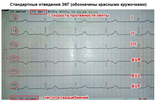
The significance of the leads is that each of them registers the passage of an electrical impulse through a certain area of the heart. Thanks to this, you can obtain information about:
- How is the heart located in chest(electrical axis of the heart, which coincides with the anatomical axis).
- What is the structure, thickness and nature of blood circulation of the myocardium of the atria and ventricles.
- How regularly do impulses occur in the sinus node and are there any interruptions?
- Are all impulses carried out along the paths of the conducting system, and are there any obstacles in their path?
What does an electrocardiogram consist of?
If the heart had the same structure of all its departments, nerve impulses would pass through them in the same time. As a result, on the ECG, each electrical discharge would correspond to only one tooth, which reflects the contraction. The period between contractions (impulses) on the EGC looks like an even horizontal line, which is called an isoline.
The human heart consists of right and left halves, in which the upper part is the atria, and the lower part is the ventricles. Because they have different sizes, thickness and are separated by partitions, the exciting impulse passes through them at different speeds. Therefore, different waves corresponding to a specific part of the heart are recorded on the ECG.
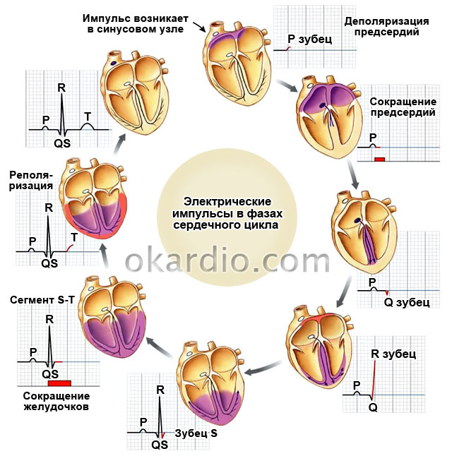
What do the teeth mean?
The sequence of propagation of systolic excitation of the heart is as follows:
- The origin of electric pulse discharges occurs in the sinus node. Since it is located close to the right atrium, it is this section that contracts first. With a slight delay, almost simultaneously, it decreases left atrium. On the ECG, such a moment is reflected by the P wave, which is why it is called atrial. It faces up.
- From the atria, the discharge passes to the ventricles through the atrioventricular (atrioventricular) node (a collection of modified myocardial nerve cells). They have good electrical conductivity, so delays in the node do not normally occur. This is displayed on the ECG as the P-Q interval - a horizontal line between the corresponding teeth.
- Excitation of the ventricles. This part of the heart has the thickest myocardium, so the electrical wave travels through them longer than through the atria. As a result, the highest wave appears on the ECG - R (ventricular), facing upward. It may be preceded by a small Q wave, the apex of which faces in the opposite direction.
- After the completion of ventricular systole, the myocardium begins to relax and restore energy potentials. On the ECG it looks like an S wave (facing down) - complete absence excitability. After it comes a small T wave, facing upward, preceded by a short horizontal line - the S-T segment. They indicate that the myocardium has fully recovered and is ready to make another contraction.


Since each electrode attached to the limbs and chest (lead) corresponds to a specific part of the heart, the same teeth look different in different leads - they are more pronounced in some, and less in others.
How to decipher a cardiogram
Sequential ECG interpretation in both adults and children involves measuring the size, length of the waves and intervals, assessing their shape and direction. Your actions with decryption should be as follows:
- Unfold the paper with the recorded ECG. It can be either narrow (about 10 cm) or wide (about 20 cm). You will see several jagged lines running horizontally, parallel to each other. After a short interval in which there are no teeth, after the recording is interrupted (1–2 cm), the line with several complexes of teeth begins again. Each such graph displays a lead, so it is preceded by a designation of which lead it is (for example, I, II, III, AVL, V1, etc.).
- In one of the standard leads (I, II or III) in which the R wave is the highest (usually the second), measure the distance between three successive R waves (R-R-R interval) and determine the average value (divide number of millimeters per 2). This is necessary to calculate the heart rate per minute. Remember that these and other measurements can be made with a millimeter ruler or by calculating the distance using an ECG tape. Each large cell on the paper corresponds to 5 mm, and each dot or small cell inside it corresponds to 1 mm.
- Assess the spaces between the R waves: are they the same or different? This is necessary in order to determine the regularity of the heart rhythm.
- Sequentially evaluate and measure each wave and interval on the ECG. Determine their suitability normal indicators(table below).

Important to remember! Always pay attention to the speed of the tape - 25 or 50 mm per second. This is fundamentally important for calculating heart rate (HR). Modern devices indicate heart rate on a tape, and there is no need to count.
How to count your heart rate
There are several ways to count the number of heartbeats per minute:
- Typically, the ECG is recorded at a speed of 50 mm/sec. In this case, you can calculate your heart rate (heart rate) using the following formulas:
Heart rate=60/((R-R (in mm)*0.02))
When recording an ECG at a speed of 25 mm/sec:
Heart rate=60/((R-R (in mm)*0.04)
- You can also calculate the heart rate on a cardiogram using the following formulas:
- When recording at 50 mm/sec: HR = 600/average number of large cells between R waves.
- When recording at 25 mm/sec: HR = 300/average of the number of large cells between the R waves.

What does an ECG look like normally and with pathology?
What a normal ECG and wave complexes should look like, what deviations occur most often and what they indicate are described in the table.
Important to remember!
- One small cell (1 mm) on the ECG film corresponds to 0.02 seconds when recording at 50 mm/sec and 0.04 seconds when recording at 25 mm/sec (for example, 5 cells - 5 mm - one large cell corresponds to 1 second).
- The AVR lead is not used for evaluation. Normally, it is a mirror image of standard leads.
- The first lead (I) duplicates the AVL, and the third (III) duplicates the AVF, so they look almost identical on the ECG.

| ECG parameters | Normal indicators | How to decipher deviations from the norm on a cardiogram, and what they indicate |
|---|---|---|
| Distance R–R–R | All spaces between R waves are equal | Different intervals may indicate atrial fibrillation, heart block |
| Heart rate | In the range from 60 to 90 beats/min | Tachycardia – when heart rate is more than 90/min Bradycardia – less than 60/min |
| P wave (atrial contraction) | Facing upward like an arc, about 2 mm high, precedes each R wave. May be absent in III, V1 and AVL | High (more than 3 mm), wide (more than 5 mm), in the form of two halves (double-humped) - thickening of the atrial myocardium |
| Generally absent in leads I, II, FVF, V2 – V6 – the rhythm does not come from the sinus node | ||
| Several small sawtooth-shaped teeth between the R waves – atrial fibrillation | ||
| P–Q interval | Horizontal line between P and Q waves 0.1–0.2 seconds | If it is elongated (more than 1 cm when recording 50 mm/sec) – hearts |
| Shortening (less than 3 mm) – | ||
| QRS complex | Duration is about 0.1 sec (5 mm), after each complex there is a T wave and there is a horizontal line gap | Expansion of the ventricular complex indicates hypertrophy of the ventricular myocardium, bundle branch block |
| If there are no gaps between high complexes facing upward (they go continuously), this indicates either ventricular fibrillation | ||
| Looks like a “flag” – myocardial infarction | ||
| Q wave | Downward facing, less than ¼ R deep, may be absent | A deep and wide Q wave in standard or chest leads indicates acute or suffered a heart attack myocardium |
| R wave | The highest, facing upward (about 10–15 mm), pointed, present in all leads | It may have different heights in different leads, but if it is more than 15–20 mm in leads I, AVL, V5, V6, this may indicate. A jagged R at the top in the shape of the letter M indicates a bundle branch block. |
| S wave | Available in all leads, facing down, pointed, can have different depths: 2–5 mm in standard leads | Normally, in the chest leads its depth can be as many millimeters as the height R, but should not exceed 20 mm, and in leads V2–V4 the depth of S is the same as the height of R. Deep or jagged S in III, AVF, V1, V2 – left ventricular hypertrophy. |
| Segment S–T | Corresponds to the horizontal line between the S and T waves | Deviation of the electrocardiographic line up or down from the horizontal plane by more than 2 mm indicates coronary disease, angina or myocardial infarction |
| T wave | Facing upwards in the form of an arc with a height of less than ½ R, in V1 it may have the same height, but should not be higher | A tall, pointed, double-humped T in the standard and chest leads indicates coronary disease and heart overload |
| The T wave merging with the S–T interval and the R wave in the form of an arched “flag” indicates acute period heart attack |

Something else important
The ECG characteristics described in the table in normal and pathological conditions are only a simplified version of the decoding. A full assessment of the results and the correct conclusion can only be made by a specialist (cardiologist) who knows the extended scheme and all the intricacies of the method. This is especially true when you need to decipher an ECG in children. The general principles and elements of the cardiogram are the same as for adults. But for children different ages There are different standards. Therefore, only pediatric cardiologists can make a professional assessment in controversial and doubtful cases.
To accurately interpret changes when analyzing an ECG, you must adhere to the decoding scheme given below.
General scheme for decoding an ECG: deciphering a cardiogram in children and adults: general principles, reading the results, example of decoding.
Normal electrocardiogram
Any ECG consists of several waves, segments and intervals, reflecting the complex process of propagation of an excitation wave throughout the heart.
The shape of electrocardiographic complexes and the size of the teeth are different in different leads and are determined by the size and direction of the projection of the moment vectors EMF of the heart to the axis of one or another lead. If the projection of the torque vector is directed towards the positive electrode of a given lead, an upward deviation from the isoline is recorded on the ECG - positive waves. If the projection of the vector is directed towards the negative electrode, a deviation downward from the isoline is recorded on the ECG - negative waves. In the case when the moment vector is perpendicular to the lead axis, its projection onto this axis is zero and no deviations from the isoline are recorded on the ECG. If during the excitation cycle the vector changes its direction relative to the poles of the lead axis, then the wave becomes biphasic.
Segments and waves of a normal ECG.
Prong R.
The P wave reflects the process of depolarization of the right and left atria. In a healthy person, in leads I, II, aVF, V-V the P wave is always positive, in leads III and aVL, V it can be positive, biphasic or (rarely) negative, and in lead aVR the P wave is always negative. In leads I and II, the P wave has maximum amplitude. The duration of the P wave does not exceed 0.1 s, and its amplitude is 1.5-2.5 mm.
P-Q(R) interval.
The P-Q(R) interval reflects the duration of atrioventricular conduction, i.e. time of excitation propagation through the atria, AV node, His bundle and its branches. Its duration is 0.12-0.20 s and in a healthy person depends mainly on the heart rate: the higher the heart rate, the shorter the P-Q(R) interval.
Ventricular QRST complex.
The ventricular QRST complex reflects the complex process of propagation (QRS complex) and extinction (RS-T segment and T wave) of excitation throughout the ventricular myocardium.
Q wave.
The Q wave can normally be recorded in all standard and enhanced unipolar limb leads and in precordial leads V-V. The amplitude of the normal Q wave in all leads, except aVR, does not exceed the height of the R wave, and its duration is 0.03 s. In lead aVR in a healthy person, a deep and wide Q wave or even a QS complex may be recorded.
R wave
Normally, the R wave can be recorded in all standard and enhanced limb leads. In lead aVR, the R wave is often poorly defined or absent altogether. In the chest leads, the amplitude of the R wave gradually increases from V to V, and then decreases slightly in V and V. Sometimes the r wave may be absent. Prong
R reflects the spread of excitation along the interventricular septum, and the R wave - along the muscles of the left and right ventricles. The interval of internal deviation in lead V does not exceed 0.03 s, and in lead V - 0.05 s.
S wave
In a healthy person, the amplitude of the S wave in various electrocardiographic leads fluctuates within wide limits, not exceeding 20 mm. With a normal position of the heart in the chest in the limb leads, the S amplitude is small, except in lead aVR. In the chest leads, the S wave gradually decreases from V, V to V, and in leads V, V it has a small amplitude or is absent altogether. The equality of the R and S waves in the precordial leads (“transition zone”) is usually recorded in lead V or (less often) between V and V or V and V.
The maximum duration of the ventricular complex does not exceed 0.10 s (usually 0.07-0.09 s).
RS-T segment.
The RS-T segment in a healthy person in the limb leads is located on the isoline (0.5 mm). Normally, in chest leads V-V there may be a slight displacement of the RS-T segment upward from the isoline (no more than 2 mm), and in leads V - downward (no more than 0.5 mm).
T wave
Normally, the T wave is always positive in leads I, II, aVF, V-V, and T>T, and T>T. In leads III, aVL and V, the T wave can be positive, biphasic or negative. In lead aVR, the T wave is normally always negative.
Q-T interval(QRST)
The Q-T interval is called electrical ventricular systole. Its duration depends primarily on the number of heart contractions: the higher the rhythm frequency, the shorter the proper Q-T interval. The normal duration of the Q-T interval is determined by the Bazett formula: Q-T=K, where K is a coefficient equal to 0.37 for men and 0.40 for women; R-R – duration of one cardiac cycle.
Electrocardiogram analysis.
The analysis of any ECG should begin with checking the correctness of its registration technique. First, you need to pay attention to the presence of various interferences. Interference that occurs during ECG recording:
a - induction currents - network induction in the form of regular oscillations with a frequency of 50 Hz;
b - “swimming” (drift) of the isoline as a result of poor contact of the electrode with the skin;
c - interference caused by muscle tremor (irregular frequent vibrations are visible).
Interference occurring during ECG recording
Secondly, it is necessary to check the amplitude of the control millivolt, which should correspond to 10mm.
Thirdly, the speed of paper movement during ECG recording should be assessed. When recording an ECG at a speed of 50 mm, 1 mm on paper tape corresponds to a time period of 0.02 s, 5 mm - 0.1 s, 10 mm - 0.2 s, 50 mm - 1.0 s.
I.Heart rate and conduction analysis:
1) assessment of the regularity of heart contractions;
2) counting the number of heartbeats;
3) determination of the source of excitation;
4) assessment of the conductivity function.
II. Determination of heart rotations around the anteroposterior, longitudinal and transverse axes:
1) determination of the position of the electrical axis of the heart in the frontal plane;
2) determination of the rotation of the heart around the longitudinal axis;
3) determination of the rotation of the heart around the transverse axis.
III. Analysis of the atrial P wave.
IV. Analysis of the ventricular QRST complex:
1) analysis of the QRS complex,
2) analysis of the RS-T segment,
3) analysis of the Q-T interval.
V. Electrocardiographic report.
I.1) Heart rate regularity is assessed by comparing the duration of R-R intervals between successively recorded cardiac cycles. The R-R interval is usually measured between the tops of the R waves. Regular, or correct, heart rhythm is diagnosed if the duration of the measured R-R is the same and the spread of the obtained values does not exceed 10% of the average duration R-R. In other cases, the rhythm is considered abnormal (irregular), which can be observed with extrasystole, atrial fibrillation, sinus arrhythmia, etc.
2) With the correct rhythm, heart rate (HR) is determined by the formula: HR=.
If the ECG rhythm is abnormal, in one of the leads (most often in standard lead II) it is recorded longer than usual, for example, for 3-4 seconds. Then the number of QRS complexes recorded in 3 seconds is counted and the result is multiplied by 20.
In a healthy person, the resting heart rate ranges from 60 to 90 per minute. An increase in heart rate is called tachycardia, and a decrease is called bradycardia.
Assessing the regularity of rhythm and heart rate:
a) correct rhythm; b), c) incorrect rhythm
3) To determine the source of excitation (pacemaker), it is necessary to evaluate the course of excitation in the atria and establish the ratio of the R waves to the ventricular QRS complexes.
Sinus rhythm characterized by: the presence in standard lead II of positive H waves preceding each QRS complex; constant identical shape of all P waves in the same lead.
In the absence of these signs, various variants of non-sinus rhythm are diagnosed.
Atrial rhythm(from the lower parts of the atria) is characterized by the presence of negative P, P waves and the following unchanged QRS complexes.
Rhythm from AV connection characterized by: the absence of a P wave on the ECG, merging with the usual unchanged QRS complex, or the presence of negative P waves located after the normal unchanged QRS complexes.
Ventricular (idioventricular) rhythm characterized by: slow ventricular rhythm (less than 40 beats per minute); the presence of widened and deformed QRS complexes; lack of a natural connection between QRS complexes and P waves.
4) For a rough preliminary assessment of the conduction function, it is necessary to measure the duration of the P wave, the duration of the P-Q(R) interval and the total duration of the ventricular QRS complex. An increase in the duration of these waves and intervals indicates a slowdown in conduction in the corresponding part of the conduction system of the heart.
II. Determination of the position of the electrical axis of the heart. There are the following options for the position of the electrical axis of the heart:
Bailey's six-axis system.
A) Determining the angle by graphical method. The algebraic sum of the amplitudes of the QRS complex waves is calculated in any two leads from the limbs (standard leads I and III are usually used), the axes of which are located in the frontal plane. A positive or negative value of an algebraic sum on an arbitrarily chosen scale is plotted on the positive or negative part of the axis of the corresponding lead in the six-axis Bailey coordinate system. These values represent projections of the desired electrical axis of the heart onto axes I and III of standard leads. From the ends of these projections, perpendiculars to the axes of the leads are restored. The intersection point of the perpendiculars is connected to the center of the system. This line is the electrical axis of the heart.
b) Visual determination of the angle. Allows you to quickly estimate the angle with an accuracy of 10°. The method is based on two principles:
1. The maximum positive value of the algebraic sum of the teeth of the QRS complex is observed in that lead, the axis of which approximately coincides with the location of the electrical axis of the heart, and is parallel to it.
2. A complex of type RS, where the algebraic sum of the teeth is zero (R=S or R=Q+S), is written in the lead whose axis is perpendicular to the electrical axis of the heart.
With a normal position of the electrical axis of the heart: RRR; in leads III and aVL, the R and S waves are approximately equal to each other.
In a horizontal position or deviation of the electrical axis of the heart to the left: high R waves are fixed in leads I and aVL, with R>R>R; a deep S wave is recorded in lead III.
In a vertical position or deviation of the electrical axis of the heart to the right: high R waves are recorded in leads III and aVF, and R R> R; deep S waves are recorded in leads I and aV
III. P wave analysis includes: 1) measurement of P wave amplitude; 2) measurement of the duration of the P wave; 3) determination of the polarity of the P wave; 4) determination of the shape of the P wave.
IV.1) Analysis of the QRS complex includes: a) assessment of the Q wave: amplitude and comparison with the R amplitude, duration; b) assessment of the R wave: amplitude, comparing it with the amplitude of Q or S in the same lead and with R in other leads; duration of the interval of internal deviation in leads V and V; possible splitting of a tooth or the appearance of an additional one; c) assessment of the S wave: amplitude, comparing it with the R amplitude; possible widening, jagged or splitting of the tooth.
2) AtRS-T segment analysis necessary: find connection point j; measure its deviation (+–) from the isoline; measure the amount of displacement of the RS-T segment, either up or down the isoline at a point located 0.05-0.08 s from point j to the right; determine the form of possible displacement of the RS-T segment: horizontal, obliquely downward, obliquely upward.
3)When analyzing the T wave should: determine the polarity of T, evaluate its shape, measure the amplitude.
4) QT interval analysis: Duration measurement.
V. Electrocardiographic conclusion:
1) source of heart rhythm;
2) regularity of heart rhythm;
4) position of the electrical axis of the heart;
5) the presence of four electrocardiographic syndromes: a) heart rhythm disturbances; b) conduction disorders; c) hypertrophy of the myocardium of the ventricles and atria or their acute overload; d) myocardial damage (ischemia, dystrophy, necrosis, scars).
Electrocardiogram for cardiac arrhythmias
1. Disorders of automatism of the SA node (nomotopic arrhythmias)
1) Sinus tachycardia: increase in the number of heartbeats to 90-160(180) per minute (shortening R-R intervals); maintaining correct sinus rhythm (correct alternation of the P wave and the QRST complex in all cycles and a positive P wave).
2) Sinus bradycardia: decrease in the number of heartbeats to 59-40 per minute (increase in the duration of the R-R intervals); maintaining correct sinus rhythm.
3) Sinus arrhythmia: fluctuations in the duration of R-R intervals exceeding 0.15 s and associated with the respiratory phases; preservation of all electrocardiographic signs of sinus rhythm (alternating P wave and QRS-T complex).
4) Sinoatrial node weakness syndrome: persistent sinus bradycardia; periodic appearance of ectopic (non-sinus) rhythms; presence of SA blockade; bradycardia-tachycardia syndrome.
a) ECG of a healthy person; b) sinus bradycardia; c) sinus arrhythmia
2. Extrasystole.
1) Atrial extrasystole: premature extraordinary appearance of the P′ wave and the following QRST′ complex; deformation or change in the polarity of the P′ wave of the extrasystole; the presence of an unchanged extrasystolic ventricular QRST′ complex, similar in shape to ordinary normal complexes; the presence of an incomplete compensatory pause after an atrial extrasystole.
Atrial extrasystole (II standard lead): a) from the upper parts of the atria; b) from the middle parts of the atria; c) from the lower parts of the atria; d) blocked atrial extrasystole.
2) Extrasystoles from the atrioventricular connection: premature, extraordinary appearance on the ECG of an unchanged ventricular QRS′ complex, similar in shape to other QRST complexes of sinus origin; negative P′ wave in leads II, III and aVF after the extrasystolic QRS′ complex or absence of P′ wave (fusion of P′ and QRS′); the presence of an incomplete compensatory pause.
3) Ventricular extrasystole: premature extraordinary appearance on the ECG of an altered ventricular QRS complex; significant expansion and deformation of the extrasystolic QRS complex; the location of the RS-T′ segment and the T′ wave of the extrasystole is discordant to the direction of the main wave of the QRS′ complex; absence of a P wave before the ventricular extrasystole; the presence in most cases of a complete compensatory pause after a ventricular extrasystole.
a) left ventricular; b) right ventricular extrasystole
3. Paroxysmal tachycardia.
1) Atrial paroxysmal tachycardia: a sudden onset and also suddenly ending attack of increased heart rate up to 140-250 per minute while maintaining the correct rhythm; the presence of a reduced, deformed, biphasic or negative P wave before each ventricular QRS complex; normal unchanged ventricular QRS complexes; in some cases, there is a deterioration in atrioventricular conduction with the development of first degree atrioventricular block with periodic loss of individual QRS′ complexes (non-constant signs).
2) Paroxysmal tachycardia from the atrioventricular junction: a sudden onset and also suddenly ending attack of increased heart rate up to 140-220 per minute while maintaining the correct rhythm; the presence in leads II, III and aVF of negative P' waves located behind the QRS' complexes or merging with them and not recorded on the ECG; normal unchanged ventricular QRS complexes.
3) Ventricular paroxysmal tachycardia: a sudden onset and also suddenly ending attack of increased heart rate up to 140-220 per minute while maintaining the correct rhythm in most cases; deformation and widening of the QRS complex more than 0.12 s with discordant location of the RS-T segment and T wave; the presence of atrioventricular dissociation, i.e. complete separation of the rapid ventricular rhythm and normal atrial rhythm with occasionally recorded single normal unchanged QRST complexes of sinus origin.
4. Atrial flutter: the presence on the ECG of frequent - up to 200-400 per minute - regular, similar atrial F waves, having a characteristic sawtooth shape (leads II, III, aVF, V, V); in most cases, correct, regular ventricular rhythm with equal F-F intervals; the presence of normal unchanged ventricular complexes, each of which is preceded by a certain number of atrial F waves (2:1, 3:1, 4:1, etc.).
5. Atrial fibrillation: absence of P waves in all leads; the presence of random waves throughout the cardiac cycle f, having different shapes and amplitudes; waves f better recorded in leads V, V, II, III and aVF; irregular ventricular QRS complexes – irregular ventricular rhythm; the presence of QRS complexes, which in most cases have a normal, unchanged appearance.
a) coarse-wavy form; b) finely wavy form.
6. Ventricular flutter: frequent (up to 200-300 per minute), regular and identical in shape and amplitude flutter waves, reminiscent of a sinusoidal curve.
7. Ventricular fibrillation: frequent (200 to 500 per minute), but irregular waves that differ from each other various shapes and amplitude.
Electrocardiogram for conduction dysfunction.
1. Sinoatrial blockade: periodic loss of individual cardiac cycles; the increase in the pause between two adjacent P or R waves at the time of loss of cardiac cycles is almost 2 times (less often 3 or 4 times) compared to the usual P-P or R-R intervals.
2. Intraatrial block: increase in the duration of the P wave by more than 0.11 s; splitting of the P wave.
3. Atrioventricular blockade.
1) I degree: increase in the duration of the P-Q(R) interval by more than 0.20 s.
a) atrial form: expansion and splitting of the P wave; QRS is normal.
b) nodal form: lengthening of the P-Q(R) segment.
c) distal (three-bundle) form: pronounced QRS deformation.
2) II degree: loss of individual ventricular QRST complexes.
a) Mobitz type I: gradual prolongation of the P-Q(R) interval followed by loss of QRST. After an extended pause, the P-Q(R) is again normal or slightly extended, after which the entire cycle is repeated.
b) Mobitz type II: loss of QRST is not accompanied by a gradual lengthening of P-Q(R), which remains constant.
c) Mobitz type III (incomplete AV block): either every second (2:1) or two or more ventricular complexes in a row are lost (block 3:1, 4:1, etc.).
3) III degree: complete separation of atrial and ventricular rhythms and a decrease in the number of ventricular contractions to 60-30 per minute or less.
4. Block of the legs and branches of the His bundle.
1) Block of the right leg (branch) of the His bundle.
a) Complete blockade: the presence in the right chest leads V (less often in limb leads III and aVF) of QRS complexes of the rSR′ or rSR′ type, having M-shaped view, and R′ > r; the presence in the left chest leads (V, V) and leads I, aVL of a widened, often jagged S wave; increase in the duration (width) of the QRS complex by more than 0.12 s; the presence in lead V (less often in III) of depression of the RS-T segment with a convexity facing upward, and a negative or biphasic (–+) asymmetric T wave.
b) Incomplete blockade: the presence of a QRS complex of type rSr′ or rSR′ in lead V, and a slightly widened S wave in leads I and V; duration of the QRS complex is 0.09-0.11 s.
2) Blockade of the left anterior branch of the His bundle: sharp deviation of the electrical axis of the heart to the left (angle α –30°); QRS in leads I, aVL type qR, III, aVF, II type rS; the total duration of the QRS complex is 0.08-0.11 s.
3) Block of the left posterior branch of the His bundle: sharp deviation of the electrical axis of the heart to the right (angle α120°); the shape of the QRS complex in leads I and aVL is type rS, and in leads III, aVF - type qR; the duration of the QRS complex is within 0.08-0.11 s.
4) Left bundle branch block: in leads V, V, I, aVL there are widened deformed ventricular complexes of type R with a split or wide apex; in leads V, V, III, aVF there are widened deformed ventricular complexes, having the appearance of QS or rS with a split or wide apex of the S wave; an increase in the total duration of the QRS complex by more than 0.12 s; the presence in leads V, V, I, aVL of a discordant displacement of the RS-T segment with respect to the QRS and negative or biphasic (–+) asymmetric T waves; deviation of the electrical axis of the heart to the left is often observed, but not always.
5) Blockade of three branches of the His bundle: atrioventricular block I, II or III degree; blockade of two branches of the His bundle.
Electrocardiogram for atrial and ventricular hypertrophy.
1. Left atrial hypertrophy: bifurcation and increase in the amplitude of P waves (P-mitrale); an increase in the amplitude and duration of the second negative (left atrial) phase of the P wave in lead V (less often V) or the formation of a negative P; negative or biphasic (+–) P wave (non-constant sign); increase in the total duration (width) of the P wave – more than 0.1 s.
2. Right atrium hypertrophy: in leads II, III, aVF, the P waves are high-amplitude, with a pointed apex (P-pulmonale); in leads V, the P wave (or at least its first - right atrial phase) is positive with a pointed apex (P-pulmonale); in leads I, aVL, V the P wave is of low amplitude, and in aVL it can be negative (not a constant sign); the duration of the P waves does not exceed 0.10 s.
3. Left ventricular hypertrophy: an increase in the amplitude of the R and S waves. In this case, R2
4. Right ventricular hypertrophy: displacement of the electrical axis of the heart to the right (angle α more than 100°); an increase in the amplitude of the R wave in V and the S wave in V; the appearance of a QRS complex of type rSR′ or QR in lead V; signs of rotation of the heart around the longitudinal axis clockwise; downward displacement of the RS-T segment and the appearance of negative T waves in leads III, aVF, V; an increase in the duration of the interval of internal deviation in V by more than 0.03 s.
Electrocardiogram for coronary heart disease.
1. Acute stage of myocardial infarction characterized by the rapid, within 1-2 days, formation of a pathological Q wave or QS complex, displacement of the RS-T segment above the isoline and the first positive and then negative T wave merging with it; after a few days the RS-T segment approaches the isoline. At the 2-3rd week of the disease, the RS-T segment becomes isoelectric, and the negative coronary T wave sharply deepens and becomes symmetrical and pointed.
2. In the subacute stage of myocardial infarction a pathological Q wave or QS complex (necrosis) and a negative coronary T wave (ischemia) are recorded, the amplitude of which gradually decreases starting from the 20-25th day. The RS-T segment is located on the isoline.
3. Scar stage of myocardial infarction characterized by the persistence for a number of years, often throughout the patient’s entire life, of a pathological Q wave or QS complex and the presence of a weakly negative or positive T wave.
Save on social networks:The electrocardiogram reflects electrical processes only in the myocardium: depolarization (excitation) and repolarization (restoration) of myocardial cells.
Ratio ECG intervals With phases of the cardiac cycle(ventricular systole and diastole).
Normally, depolarization leads to contraction of the muscle cell, and repolarization leads to relaxation. To simplify further, instead of “depolarization-repolarization” I will sometimes use “contraction-relaxation”, although this is not entirely accurate: there is a concept “ electromechanical dissociation“, in which depolarization and repolarization of the myocardium do not lead to its visible contraction and relaxation. I wrote a little more about this phenomenon earlier .
Elements of a normal ECG
Before moving on to decoding the ECG, you need to understand what elements it consists of.

Waves and intervals on the ECG. It is curious that abroad the P-Q interval is usually called P-R.
Any ECG consists of teeth, segments And intervals.
TEETH- these are convexities and concavities on the electrocardiogram. The following waves are distinguished on the ECG:
P(atrial contraction)
Q, R, S(all 3 teeth characterize contraction of the ventricles),
T(ventricle relaxation)
U(non-permanent tooth, rarely recorded).
SEGMENTS A segment on an ECG is called straight line segment(isolines) between two adjacent teeth. The most important segments are P-Q and S-T. For example, the P-Q segment is formed due to a delay in the conduction of excitation in the atrioventricular (AV-) node.
INTERVALS The interval consists of tooth (complex of teeth) and segment. Thus, interval = tooth + segment. The most important are P-Q intervals and Q-T.

Waves, segments and intervals on the ecg. Pay attention to large and small cells (more about them below).
QRS complex waves
Since the ventricular myocardium is more massive than the atrial myocardium and has not only walls, but also a massive interventricular septum, the spread of excitation in it is characterized by the appearance of a complex complex QRS on the ECG. How to do it right highlight the teeth in it?
First of all they evaluate amplitude (sizes) of individual teeth QRS complex. If the amplitude exceeds 5 mm, the tooth indicates capital letter Q, R or S; if the amplitude is less than 5 mm, then lowercase (small): q, r or s.
The R wave (r) is called any positive(upward) wave that is part of the QRS complex. If there are several teeth, subsequent teeth indicate strokes: R, R’, R”, etc. Negative (downward) wave of the QRS complex, located before the R wave, is denoted as Q(q), and after - like S(s). If there are no positive waves at all in the QRS complex, then the ventricular complex is designated as QS.

Options for the qrs complex.
Normal tooth Q reflects depolarization of the interventricular septum, tooth R- the bulk of the ventricular myocardium, tooth S- basal (i.e. near the atria) sections of the interventricular septum. The R V1, V2 wave reflects the excitation of the interventricular septum, and R V4, V5, V6 - the excitation of the muscles of the left and right ventricles. Necrosis of areas of the myocardium (for example, with myocardial infarction ) causes the Q wave to widen and deepen, so close attention is always paid to this wave.
ECG analysis
General ECG decoding diagram
Checking the correctness of ECG registration.
Heart rate and conduction analysis:
assessment of heart rate regularity,
heart rate (HR) counting,
determination of the source of excitation,
conductivity assessment.
Determination of the electrical axis of the heart.
Analysis of the atrial P wave and P-Q interval.
Analysis of the ventricular QRST complex:
QRS complex analysis,
analysis of the RS - T segment,
T wave analysis,
Q-T interval analysis.
Electrocardiographic report.

Normal electrocardiogram.
1) Checking the correct ECG registration
At the beginning of each ECG tape there must be calibration signal- so-called reference millivolt. To do this, at the beginning of the recording, a standard voltage of 1 millivolt is applied, which should display a deviation of 10 mm. Without a calibration signal, the ECG recording is considered incorrect. Normally, in at least one of the standard or enhanced limb leads, the amplitude should exceed 5 mm, and in the chest leads - 8 mm. If the amplitude is lower, it is called reduced ECG voltage, which occurs in some pathological conditions.

Reference millivolt on the ECG (at the beginning of the recording).
2) Heart rate and conduction analysis:
assessment of heart rate regularity
Rhythm regularity is assessed by R-R intervals. If the teeth are at an equal distance from each other, the rhythm is called regular, or correct. The variation in the duration of individual R-R intervals is allowed no more than ± 10% from their average duration. If the rhythm is sinus, it is usually regular.
heart rate counting(heart rate)
The ECG film has large squares printed on it, each of which contains 25 small squares (5 vertical x 5 horizontal). To quickly calculate heart rate with the correct rhythm, count the number of large squares between two adjacent teeth R - R.
At belt speed 50 mm/s: HR = 600 / (number of large squares). At belt speed 25 mm/s: HR = 300 / (number of large squares).
On the overlying ECG, the R-R interval is approximately 4.8 large cells, which at a speed of 25 mm/s gives 300 / 4.8 = 62.5 beats/min.
At a speed of 25 mm/s each small cell equal to 0.04 s, and at a speed of 50 mm/s - 0.02 s. This is used to determine the duration of the teeth and intervals.
If the rhythm is incorrect, it is usually considered maximum and minimum heart rate according to the duration of the smallest and largest R-R interval, respectively.
An electrocardiogram (ECG) is instrumental diagnostic method, which determines pathological processes in the heart by recording cardiac electrical impulses. A graphical representation of the activity of the heart muscles under the influence of electrical impulses allows the cardiologist to timely identify the presence or development of cardiac pathologies.
ECG interpretation indicators help to determine with great certainty:
- Frequency and rhythm heart rate;
- Diagnose acute or chronic processes in the heart muscle in a timely manner;
- Disorders of the conduction system of the heart and its independent rhythmic contractions;
- See hypertrophic changes in its departments;
- Identify disturbances in water-electrolyte balance and non-cardiac pathologies (cor pulmonale) throughout the body.
The need for an electrocardiographic examination is due to the manifestation of certain symptoms:
- the presence of synchronous or periodic heart murmurs;
- syncope signs (fainting, short-term loss of consciousness);
- attacks of convulsive seizures;
- paroxysmal arrhythmia;
- manifestations of coronary artery disease (ischemia) or infarction conditions;
- the appearance of heart pain, shortness of breath, sudden weakness, cyanosis skin in patients with cardiac diseases.
ECG studies are used to diagnose systemic diseases, monitor patients under anesthesia or before surgery. Before clinical examination of patients who have crossed the 45-year mark.
An ECG examination is mandatory for persons undergoing a medical examination (pilots, drivers, machinists, etc.) or associated with hazardous work.
The human body has high electrical conductivity, which allows the potential energy of the heart to be read from its surface. Electrodes connected to various parts of the body help with this. In the process of excitation of the heart muscle by electrical impulses, the voltage difference oscillates between certain lead points, which is recorded by electrodes located on the body - on the chest and limbs.
 A certain movement and amount of tension during systole and diastole (contraction and relaxation) of the heart muscle changes, the tension fluctuates, and this is recorded on a chart paper tape with a curved line - teeth, convexity and concavity. Electrodes placed on the limbs (standard leads) create signals and form the tops of triangular teeth.
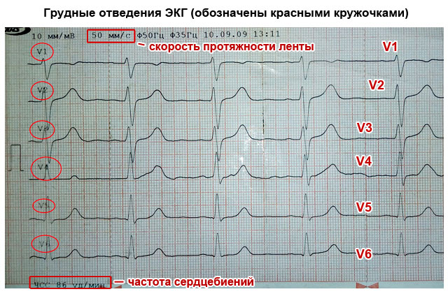
Six leads located on the chest display cardiac activity in a horizontal position - from V1 to V6.
On the limbs:
- Lead (I) – displays the voltage level in the intermediate circuit of the electrodes located on the left and right wrist (I=LR+PR).
- (II) – records on the tape the electrical activity in the circuit – ankle of the left leg + wrist of the right hand).
- Lead (III) – characterizes the voltage in the chain of fixed electrodes of the wrist of the left hand and ankle of the left leg (LR + LN).
If necessary, additional leads are installed, reinforced ones - “aVR”, “aVF” and “aVL”.


Interpretation of ECG diagram, photo
The general principles of deciphering a cardiac cardiogram are based on the readings of the elements of the cardiography curve on the chart tape.
The teeth and bulges on the diagram are indicated by capital letters of the Latin alphabet - “P”, “Q”, “R”, “S”, “T”
- The convexity (wave or concavity) of the “P” reflects the function of the atria (their excitation), and the entire complex of the upward-pointing wave is the “QRS”, the greatest spread of the impulse through the cardiac ventricles.
- The “T” convexity characterizes the restoration of the potential energy of the myocardium (the middle layer of the heart muscle).
- When deciphering ECGs in adults, special attention is paid to the distance (segment) between adjacent elevations - “P-Q” and “S-T”, which reflect the delay of electrical impulses between the cardiac ventricles and the atrium, and the “TR” segment - relaxation of the heart muscle in the interval (diastole) .
- The intervals on the cardiographic line include both elevations and segments. For example - “P-Q” or “Q-T”.
Each element in the graphic image indicates certain processes occurring in the heart. It is by the indicators of these elements (length, height, width), location relative to the isoline, features, according to the various locations of electrodes (leads) on the body that the doctor can identify the affected areas of the myocardium, based on the readings of the dynamic aspects of the energy of the heart muscle.
Interpretation of ECG - the norm in adults, table
Analysis ECG result decoding is carried out by assessing the data in a certain sequence:
- Determination of heart rate indicators. With the same interval between the “R” teeth, the indicators correspond to the norm.
- The heart rate is calculated. This is determined simply - the ECG recording time is distributed by the number of cells in the interval between the “R” teeth. With a good cardiogram of the heart, the frequency of contractions of the heart muscle should be within the limits not exceeding 90 beats/min. A healthy heart should have sinus rhythm, it is determined mainly by the elevation of “P”, reflecting the excitation of the atria. In terms of wave motion, this normal indicator is 0.25 mV with a duration of 100 ms.
- The norm for the size of the depth of the “Q” wave should not be more than 0.25% of the fluctuations in the elevation of “R” and the width of 30 ms.
- The latitude of oscillations of the “R” elevation, during normal heart function, can be displayed with a large range ranging from 0.5-2.5 mV. And the activation time of excitation above the zone of the right cardiac chamber - V1-V2 is 30 ms. Above the left chamber zone – V5 and V6, it corresponds to 50 ms.
- According to the maximum length of the “S” wave, its normal dimensions at the greatest abduction cannot cross the threshold of 2.5 mV.
- The amplitude of the oscillations of the “T” elevation, which reflects the restorative cellular processes of the initial potential in the myocardium, should be equal to ⅔ of the oscillations of the “R” wave. The normal interval (width) of the "T" elevation can vary (100-250) ms.
- The normal width of the ventricular excitation complex (QRS) is 100 ms. It is measured by the interval between the beginning of the “Q” and the end of the “S” teeth. The normal amplitude of the duration of the “R” and “S” waves is determined by the electrical activity of the heart. The maximum duration should be within 2.6 mV.
| ECG decoding for adults norm in the table | |
| Index | Meaning |
| QRS | 0.06-0.1 s |
| P | 0.07-0.11 s |
| Q | 0.03 s |
| T | 0.12-0.28 s |
| P.O. | 0.12-0.2 s |
| Heart rate | 60-80 beats minute |
Interpretation of ECG in children, normal indicators
An electrocardiogram in children, as practice shows, is not much different from normal values in adult patients. But certain physiological age characteristics may change some indicators. In particular, heart rate. In young children under 3 years old, they can range from 100 to 110 contractions/minute. But already at puberty, it is equal to adult indicators (60-90).
Normally, when deciphering an ECG of the heart in children, the passage of electrical impulses through the parts of the heart (in the range of elevations P, QRS, T) varies from 120 to 200 ms.
The ventricular excitation rate (QRS) is determined by the width of the interval between the “Q” and “S” waves and should not exceed the boundaries of 60-100 ms.
Particular attention is paid to the size (excitation activity) of the right ventricle (V1-V2). In children this figure is higher than in the left ventricle. With age, the indicators return to normal.
- Quite often, ECGs in children show thickening, splitting, or notching on the “R” elevations. Such a symptom in the cardiogram of adults indicates tachycardia and bradycardia, and in children it is a completely common condition.
But there are indications of a bad cardiogram hearts that indicate the presence or progression pathological processes in heart. Much depends on the child’s individual performance. In addition, interruption or slowing of the normal heart rhythm occurs in children who experience chest pain, dizziness, common signs instability of blood pressure or disturbances in coordination.
If an ECG examination of a child reveals that the heart rate exceeds 110 beats/min. - this is an alarming signal indicating the development of tachycardia.
Need to immediately reduce physical exercise in the child and protect him from nervous overexcitation. In children, such symptoms may be temporary, but if measures are not taken, tachycardia will develop into a permanent problem.
Example ECG - Atrial fibrillation


